Please visit the SVPwiki
| Check out the SVPwiki | SVP Cosmology 2.3 |
(Formulae and images not yet
included in this web
page.)
Please visit the SVPwiki for an updated version of these pages.
|
|
Abstract The Keely Motor has been the subject of endless discussion over the past 120 years. John Ernst Worrell Keelys original patent was filed with the US Patent Office in 1872 and to this day resides in the Reserve section under Motors, Hydropneumatic and not generally available to the public. During all these years no indication of any kind was ever given as to its mode of function, its energy source or any principle of operation. In fact this motor was on display in The Franklin Institute in Philadelphia for many years labeled a perpetual motion machine. How does it work? What principle of physics is used in its design? Can these concepts be used today? This paper reveals for the first time answers to most of these questions. The answers are found in principles of water hammer, (cavitation, implosion) and vibration physics. |
Introduction
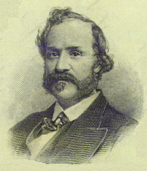
Did the Keely Motor work? It worked well enough that the promoters of The Keely Motor Company of Philadelphia, Pennsylvania raised approximately $6,000,000 in capital from sales of stock. This story is legendary in history and its implications for society. The motor was analyzed by engineers and scientists alike. All professed that it did indeed work but operated on principles they did not recognize nor understand. Small wonder then that Mr. Keely had such a terrible time convincing his peers that he really had something viable. Now, 120 years later, we can look back and begin to unravel what it was this incredible inventor created.
This motor evidently operated for the first time around the year 1870. Water hammer was not mentioned in scientific literature until the late 1880s and cavitation even later. Thus it was not likely engineers were too familiar with the concept and principles. That the machine was designed to work with water hammer can not be doubted once the basic idea is understood.
A major question right up front: Is there really sufficient energy in water hammer or cavitation to drive a prime mover type device? The answer is a resounding YES! The following contains engineering and physical substantiations of this premise.
General Overview
The general idea of this motor and its functions is, on the whole, quite simple. However these seemingly simple things can be quite complex to explain or master. The motor uses several principles of hydrodynamics, mechanics and vibration physics. These, as will be seen, are coordinated and choreographed in a simple and beautiful manner.
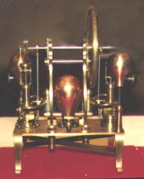
The first device on the motor is the Pulsating Chamber. This device, situated in the center of the motor, functions not unlike that of the human heart. It draws in water from an outside reservoir, not part of the motor, and pressurizes this water as it pumps it to the two sides of the machine.
The next device encountered is the One Way Check Valves located on either side of the Pulsating Chamber. Their function is quite like any ordinary one way check valve in that they allow water to pass from the Pulsating Chamber through themselves to the two opposing piston assemblies while prohibiting water to pass in the reverse direction.
Next are two piston and cylinder assemblies. The two piston assemblies are somewhat different. The only real similarity between them is the valve assemblies and this is an assumption as they have not yet been disassembled for examination. The piston assembly on the right receives the pressurized water from the Pulsating Chamber and captures or stores it in the lower Pressure Piston unit. As the valve rocks into the open position this pressurized water is allowed to escape into the upper Power Piston assembly and drives the crankshaft around.
The piston assembly on the left side is not quite fully
understood. It is theorized that the water pumped with great velocity
passes the check valve and strikes the round plunger/popper head
pushing it down. This much is certain. It is assumed this water
becomes more or less atomized and maybe even polarized to a small
degree as it strikes the round surface of the plunger/popper head.
The timing sequence of this assembly is also in doubt. It may be
assumed that just as the water becomes atomized the Power Piston is
in a suction mode and draws this vapor into the Ascension Chamber
located between the round plunger/popper and the valve. When the
pulsation of the Pulsating Chamber reverses the round
plunger/popper slams against its seat and thus causes a pop against
the Ascension Chamber. This sudden closure causes several things to
happen all at once: 1) The open-at-both-ends resonator closes at one
end and increases the fundamental frequency of its interior 3 1/2
times its fundamental. These are calculated to be in the microwave
range. An increase in the frequency will tend to heat and expand the
water vapor. At this point the valve rocks into the open position and
this now pressurized vapor can push the Power Piston and cause the
crankshaft to rotate.
The Pulsating Chamber
The light bulb shaped red copper colored object in the center of the motor is a marvelous piece of engineering and machine work. It is totally hollow and devoid of any moving mechanism. The two tubes protruding from its base are straight tubes passing completely through the bulb. Each tube has a small (approximately 1/2") hole drilled through in the center of its length. The base of the bulb is open and a seal is used to avoid leakage where it attaches to the motors base plate. An exceedingly simple design and construction. See illustration #3.
The function of the mechanism is quite simple. It takes in a small amount of water which level is only a little above the altitude of the higher tube traversing its base. This first quantity of water is introduced into the machine by rotating the flywheel by hand a few turns. This action draws the right hand piston up and by the vacuum thus created draws water into the bulb and then into the tubing connecting the one way check valves and then into the pressure piston assembly.
When the valve closes as the crank shaft is turned the water flow stops. The check valves close and the water flow between the bulb and check valves begins to oscillation or pulsate. Once this pulsation begins within the bulb it becomes as a resonator and creates a standing wave within itself by the alternating compression and rarefaction of the air and water contained within itself.
This standing wave, like all waves, has two main zones of polarizations. There will be two predominate zones created within this sphere shaped resonator. One will be positive and therefore a zone of high pressure. The other will be negative and as such is a zone of low pressure. The high pressure zone coincides with the outlet tube opening centered within the bulb. The low pressure zone coincides with the intake tube opening located within its center within the bulb. The end result of these exact placements is a suction pump and a pressure pump having no moving parts! A distant verification of this analysis can be seen in a recent NASA Tech paper(9) showing a novel pump design which uses a transducer and the wave guides of the fluid channel as part of the pumping mechanism. The difference between Keelys design and NASAs design is the latter uses a transducer to create the pulsating motions and the former uses the containing vessel itself. Keelys is the simpler design.
The Valves
One of the more important mechanical arrangements of the motor are the valves located on each end of the machine. The housings and valve cores are made of solid yellow brass machined to very fine tolerances. Please see illustration #2. Each valve has a pressure plate and set screw on the outside which allows adjustment to the clearance between core and housing.
Keely was a mechanical genius in that whenever he could combine several functions into a single mechanism he readily did so. This valve is a very good example. First it is a rotary valve designed to stop and start a flow of high pressure, high velocity water in one direction. Secondly, it then rotated and allowed the flow of low pressure, low velocity water to flow in a new direction in the exhaust mode. Thirdly the valves acted as gate valves which because of their design opened and closed abruptly thus creating water hammer as desired.
Because of the simple design the valve took an exceedingly small quantity of work to open and close it. This work was done by the use of an offset rocker arm. This attachment arrangment allowed for fine timing coordinated with the crankshaft which is absolutely essential to the proper functioning of this motor design.
The Valve Functions
The two images below show how pressurized input water is channeled through the valve assemblies and then how the exhausted water is drained from the system.
What is not shown here is the water hammer taking place every time the valves close. This water hammer shock wave travels back through the Pressure Piston assembly and stops when it encounteres the One Way Check Valves. It is the impetuous of the shock wave against the check valve balls that slam them shut thus causing the pulsations which are amplified in the Pulsating Chamber. All these mechanisms work together synchronously to make the whole work as a unit.
It is theorized that the valves also create a down stream water hammer as the water exits the valve assembly on its way into the Power Piston assembly. This idea seems very plausible but needs to be verified with more study and, if possible, experimentation.
Under ideal circumstances the pressure accumulated in the Pressure Piston assembly would, within just a few successive water hammers, reach infinity. The rapid geometric additive synthesis of amplitude would take place in virtue of the timing of the closing of the valve. The particular design on these valves allows fine adjustments for timing and adjusting of sequential events. The particular designs and mechanisms on this motor allow adjustments for performance at any desired level.
The Ascension Chamber
The Ascension Chamber is located between the valve and the phase changer plunger/popper/piston assembly on the left side of the motor. This side of the motor has caused more hours of contemplation and thought than all the rest of the motor and all aspects of its operation have not yet been determined to my satisfaction. But some things have been figured out and these are fairly certain. One of these is the so-called Ascension Chamber so named by George Hull as we brain stormed its purpose and hit on the idea that its primary and probably only function is to raise the rate of vibration of the water vapor traveling through it.
Here again Keely designed and constructed a marvelously simple mechanism for creating a high end function. This chamber is approximately 3/4" long by 7/16" wide and +/- 1/2" high. Its shape is rectangular with flat, straight walls. In fact its design reminds one of our modern day microwave guides and this proves to be a clue to its function. Water vapor is drawn into this chamber and as the plunger/popper closes the intake port from below the standing waves in this chamber immediately increase in frequency and amplitude. See illustration #4.
If we quantize the fundamental of this chamber to 1 while it is an open tube resonator its frequency ascends or increases 3 1/2 times when the chamber is closed on one end. The wave length begins at approximately 1/2" (1.27 cm) and instantly ascends to +/- 1/7" (.36 cm). These wave lengths are typical of microwave dimensions. Water subjected to microwave frequencies tends to polarize, boil and then vaporize (phase change). In other words, the liquid water is given an impulse to expand and thereby create increased pressurizations.
Cavitation = Implosion
It has been found that so-called IMPLOSION is in fact what conventional physics refers to as CAVITATION when considering microscopic levels of activity. During the processes involved in water hammer this phenomena is found to be a significant aspect of the alternately high and low pressure surges.
Generally speaking cavitation is implosion on a microscopic level while implosion is cavitation on a macroscopic level. Both levels of activity are present in water or fluid hammer situations. A simple working definition of cavitation is: The sudden release of pressure on a liquid causing the liquid to phase change into a vapor. It can be argued that this process is actually an instantaneous acceleration of the elementary particulate constructs of the molecular substance under investigation. Within the conventional Theory of Relativity it is shown that the faster an object moves the denser it gets. The denser something gets the smaller it becomes and the more energy it contains and/or releases. So here is a possible explanation of where extra energy is derived in the ordinary cavitation process. Phase change is represented in the Sympathetic Vibratory Physics paradigm by an increase or decrease in size, frequency, density, velocity and energy. It is viewed that particles do not simply taken on or release electrons - they associate or dissociate (which creates the differences above mentioned) instantaneously. In other words, these elementary particles go from one state to another as a result of modulations and or other interferences to their own structural chords whereby they can associate or dissociate respectively. Several coincidental elementary particles will associate to form a larger, slower and less energetic particle. A larger particle may dissociate into three or many more particles. Both of these processes are known to release immense quantities of energy in the form of heat, light and shock waves (polarizations).
These changes in state are sometimes referred to as realms or dimensions. In other words one group of particles sorted by size, energy and chord signatures as opposed to other similarly classed particles. See illustration #1a and 1b. This being the case there are infinite numbers of dimensions of which only eight have been partially studied. Of these eight only five have been recognized by conventional science. All eight were investigated by John Keely in the last 1880s.
It is further noted that without a comprehensive paradigm of how elementary particles behave under alternate pressure and temperature changes little makes much sense when working with cavitation, implosion or water hammer phenomena. In fact the only known book on cavitation is replete with disclaimers insofar as scientific explanations of the observed phenomena found in cavitation processes. The orthodox engineers do not know where all the extra energy is coming from. And they have measured energy releases in the order of 8,000K during bubble collapse. As has just been explained - the extra energy is released from the sub-atomic realms during phase changes of the fluids under hammer or cavitation processes.
Aqueous Vapor -> Etheric Vapor
It should be obvious that the water vapors first witnessed in the work with this motor led Keely to an exploration of this vapor. Eventually he learned how to dissociate the molecular state of liquid water into finer and finer vaporous states through induced phase changes. This we do today with ultrasonics and he used the very same concept but with different methods and instruments of his own devising. This fine vapor (of a particular order) he referred to as etheric vapor or ether. See illustration #1. An etheric vapor of this tenuity has some rather unique properties as have been mentioned in numerous articles on and about his work.(10) In short, it was through the intense work with this motor that Keely was lead into higher and higher realms of applied technology which eventually culminated in his greatest work with Negative Attraction.
"The collapse of the smaller vapor filled cavities causes many extreme results as the intensity of the resulting shock wave may be considerably greater than the originating action. As an analogy with an explosion, the initiation of the cavities is the trigger action while their collapse is the explosion." (1)
"It has been shown that rectification of the gas diffusion occurs because the surface area of the bubble varies during the sound pressure cycle. During the positive half-cycle the solution is undersaturated and gas diffuses out of the bubble; during the negative half-cycle it is supersaturated and gas flows in. But the surface area is larger during the negative half than during the positive half-cycle, so that there is an excess influx. If the rate of sonically induced diffusion into the bubble exceeds the rate which the gas diffuses because of the excess pressure resulting from the surface tension, the bubble grows in size." (2)
"Cavitation in a tube can be explained according to Bernoullis equation.
 |
Water hammer is the rise in pressure that occurs when the water flow in a pipe line or closed conduit is reduced or stopped, regardless of how this flow is checked. Hammer can occur in any line carrying liquids. Usually, the problem is important only in water lines.
The classical water-hammer problem is that of protecting
penstocks
that supply water to water turbines. If the flow in the penstock is
suddenly reduced by action of the gates controlling the water flow to
the turbines, the penstock pressure at the gate immediately rises,
the drops below the initial pressure, and continues to surge in
regular periods until friction damps the surge out.
Pump-discharge-lines pressures will surge in the same way if all the operating pumps are stopped at once, except that the initial surge which occurs at the pumping end of the line is downward. The rise in pressure following the downward surge may be sufficient to rupture the pipe or pull the line apart unless protection is provided.
The formulas most useful in water-hammer problems are (ASME, ASCE symbols)
Period of pipe line = 2L/a = one interval, seconds
where a = the velocity of the pressure wave in the pipe line, fps.
(This is the velocity of sound in the water of the the pipe
line.)
K = the bulk modulus of the liquid in the pipe line, psi (approx. 300,000 for water)
E = Youngs modulus for the pipeline material psi (30 million for steel)
d = the diameter of the pipe
e = the wall thickness of the pipe; d and e are always in the same units, i.e., both feet or both inches.
hmax = the maximum pressure rise (or drop) that can occur if the water flow is stopped instantly and there are no complicating features such as nonuniform pipe, branch lines, etc. The unit hmax of the formula is in fact of the liquid flowing.
V0 = The velocity in the pipe line just previous to the disturbance causing water hammer, fps
g = gravity, ft/sec2
L = the length of the pipe line, ft
Other terms used in the argument are:
h = the hammer pressure actually developed, ft
H0 = The operating or steady-state pressure in the pipe line just previous to the disturbance causing water hammer, ft
T = the actual time in which flow is stopped, sec
The value of a normally is somewhere between 3,000 and 3,500 fps. An accurate value usually is not needed for estimating surges in pump discharge lines.
The maximum water-hammer pressure which can occur in a simple pipe system is hmax, but this is not the maximum pressure in the pipe line because hmax adds to H0 the existing pressure in the line just previous to the disturbance. The maximum pressure existing is, then hmax plus H0, and if H0 is near the design pressure, it may be noted that rupturing pressures may occur. The water-hammer pressure hmax is alternately both positive and negative. When negative, the minimal pressure is H0-hmax. Obviously, the pipeline pressure cannot reduce below zero absolute. If the downward surge carries to zero, vacuum will form, and the collapse of this vacuum may cause a major water-hammer blow. It may be noted that hmax is independent of the length of the line and depends only on the water and the wave velocities. The value of hmax is usually between 40 and 45 psi per fps of water velocity destroyed.
The period of the pipe line, 2L/a is, by inspection, merely twice the length of the line divided by the wave velocity. It is the time it takes the pressure wave front to travel from the point of origin to the end of the line or other reflection point back to the origin. The wave of rarefaction, or subnormal pressure wave, also takes 2L/a sec to make the round trip. The time by stop watch between two crests of the pressure wave is then 4L/a sec. The value of 2L/a is important because the actual hammer h is reduced below hmax if the time it takes the flow to stop is greater than 2L/a. This is true because the subnormal phase of the wave reaches the point of origin before the pressure wave has ceased to build up and adds geometrically to the pressure wave. The value of h is for ordinary lines about equal to
with the understanding that in this formula T cannot be less than 2L/a. This formula holds reasonably well except for lines of high velocities and low pressures, in which case h is much increased. In general, T should be five to ten times the value of 2L/a to eliminate destructive water hammer.
On power failure, the pressure drop at the pumps is never hmax except for very long lines of high H0. Short lines, except those of high water velocities, have very little pressure drop since T is large compared to 2L/a. Such lines usually need no hammer protection. For intermediate lines the pressure drop on power failure is about one-half aV0/g. The subsequent pressure rise may be slightly more than that unless a vacuum has formed, in which case nearly the full water hammer develops. (5)
It is found that the sum of pressure and kinetic energy in a flowing liquid is constant. Thus the velocity of a liquid passing through a restriction may become so high that the hydrodynamical pressure is reduced to the vapor tension." (3)
"Lord Raleigh in 1917, calculated the pressure developed during the collapse of a spherical cavity. His equation was
where
P pressure at infinity external atmospheric pressure
R0 initial radius of the cavity
b the coefficient of compressibility
P and R correlated pressure and radius of the cavity during the collapse
Calculation of the above equation shows that pressure of thousands of atmospheres may be developed at the moment when the cavity collapses to a small fraction of the original diameter. Such collapses are, therefore, bound to cause enormous mechanical effects, as high kinetic energies are being concentrated at very small spots." (4)
Water hammer is the series of shocks, sounding like hammer blows, produced by suddenly checking the flow of water in a pipe. If a valve, turbine gate, or faucet is suddenly closed, kinetic energy of the arrested column of water is expended, if no relief devices are provided, in compressing the water and in stretching the pipe walls. Starting at the suddenly closed valve, a wave of increased pressure is transmitted back through the pipe with constant velocity and intensity. The shock pressure is not concentrated at the valve, but if a bursting pressure is produced, it may show its effects near the valve simply because it acts there first. The velocity of the pressure wave for ordinary cast-iron pipe, 2 to 6 in. in diameter, is about 4,200 fps; for a 24 in. pipe it is about 3,300 fps; it depends on the elasticity of the metal and upon the ratio of its thickness to the diameter of the pipe. If the pipe were perfectly rigid, the velocity would be that of sound through water, about 4,700 fps.
The increase of pressure is proportional to the arrested velocity of flow and to the speed of propagation of the pressure wave. This increase is about 60 psi for each foot per second of extinguished velocity for 2 to 6 in. pipes, and about 45 psi for each foot per second for 24 in. cast-iron pipe. These increases of pressure will be attained only in case the valve is closed in less time than one round trip of the pressure wave.
When the pressure wave has traveled upstream to the end of the pipe where there is a reservoir or a larger main (the whole pipe then being under increased pressure with checked flow throughout), the elasticity of the compressed water and that of the distended pipe reverse the flow at that end of the pipe, and a wave of normal pressure (that of the reservoir or main) travels downstream, the flow being progressively reversed as the compressed water expands. When this wave of normal pressure reaches the valve, the kinetic energy of the column of water with reversed flow tends to create a vacuum at the valve. There the reversed flow is checked and the checking proceeds progressively upstream accompanied by a wave of subnormal pressure. When this wave reaches the upstream end (the whole pipe then being under subnormal pressure), the greater normal pressure in the reservoir or large main starts to flow into the pipe, and a wave of normal pressure and forward flow travels downstream. When this wave reaches the valve, there is forward flow throughout the pipe, the conditions being the same as when the valve was suddenly closed, and a wave of increased pressure and of checked flow again starts upstream. A complete cycle of pressure waves and reversals of flow occupies the time required for two round trips. The amplitude of the pressure vibrations becomes less with succeeding cycles because of friction, but the time interval remains constant.
If a high-pressure wave, in its travel through the pipe, enters a branch pipe with a closed, or "dead," end, there may be a considerable increase of pressure when the wave strikes the closed end.
As the intensity of the excess pressure in the "hammer" wave depends on the amount of "extinguished" velocity, the same excess pressure is produced by suddenly reducing the velocity from 7 to 4 fps as by entirely stopping a velocity of 3 fps. If the flow is not checked rapidly, so that the wave from the first movement of the gate has time to travel upstream to the end and back again several times while the checking is in progress, the excess pressure is very much reduced. Hence, the wisdom of using slow-closing valves on long pipe lines.
The excess pressure and the speed of the pressure waves are given by the formulas:
and also:
In these formulas(6)(7):
p is the excess pressure intensity
S the speed of transmission of the pressure wave through the water in the pipe. The first two simpler formulas consider the pipe as perfectly inelastic. The last two formulas take into account the elasticity of the metal of the pipe.
V is the extinguished velocity, fps
w the weight of 1 cu ft of water
g = 32.2
E the bulk modulus of the elasticity of water = about 300,000 psi
E the linear modulus of the pipe metal = 30,000,000 psi for steel
t the thickness of the pipe metal
D internal diameter of the pipe.
The same system of units should be used throughout. If the fps system is used, the above values for E and E must be multiplied by 144. (8)
References
(1) Crawford, Alan E.,Ultrasonic Engineering with particular reference to high power applications; Butterworths Scientific Publications, 1955, London. page 26.
(2) IBID, page 30.
(3) Prakash, Satya and Ghosh, Ashim Kumar; Ultrasonics and Colloids; Scientific Research Committee, Allahabad, India, 1961. page 114
(4) IBID, page 115
(5) Segel, Joseph; Water Hammer Protection for Pump Discharge Lines, Plant Engineering Handbook; McGraw-Hill, 1950.
(6) Church, H. Wiley, Proceedings American Water Works Assn., 1904.
(7) Symposium on Water Hammer, 1933, joint ASME and ASCE.
(8) Marks, Lionel S.; Mechanical Engineers Handbook, McGraw-Hill Book Company, Inc., New York, 1951.
(9) NASA Langley Research Center, Hampton, VA 23665, Technology Utilization Office, Technical Support Package for Tech Brief LAR-14103, "An Acoustic Pump"
(10) A comprehensive list of available literature on John Keely and his work can be acquired from Delta Spectrum Research.
 |
 |
|
 |
 |